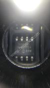
Part Number | HCTL-1101-PLC |
---|---|
Manufacturer | Broadcom Limited |
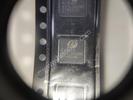
Description | IC MOTOR CONTROLLER PAR 44PLCC |
Datasheet | HCTL-1101-PLC Datasheet |
Package | 40-LCC (J-Lead) |
In Stock | 2,436 piece(s) |
Unit Price | $ 15.9500 * |
Lead Time | Can Ship Immediately |
Estimated Delivery Time | Jan 30 - Feb 4 (Choose Expedited Shipping) |
Request for Quotation |
|
Part Number # HCTL-1101-PLC (PMIC - Motor Drivers, Controllers) is manufactured by Broadcom Limited and distributed by Heisener. Being one of the leading electronics distributors, we carry many kinds of electronic components from some of the world’s top class manufacturers. Their quality is guaranteed by its stringent quality control to meet all required standards.
For HCTL-1101-PLC specifications/configurations, quotation, lead time, payment terms of further enquiries please have no hesitation to contact us. To process your RFQ, please add HCTL-1101-PLC with quantity into BOM. Heisener.com does NOT require any registration to request a quote of HCTL-1101-PLC.
Manufacturer | Broadcom Limited |
Category | Integrated Circuits (ICs) - PMIC - Motor Drivers, Controllers |
Datasheet | HCTL-1101-PLCDatasheet |
Package | 40-LCC (J-Lead) |
Series | - |
Motor Type - Stepper | Bipolar |
Motor Type - AC, DC | Brushless DC (BLDC), Brushed DC |
Function | Controller - Commutation, Direction Management |
Output Configuration | Pre-Driver |
Interface | Parallel |
Technology | CMOS |
Step Resolution | - |
Applications | General Purpose |
Current - Output | - |
Voltage - Supply | 4.75 V ~ 5.25 V |
Voltage - Load | - |
Operating Temperature | -20°C ~ 85°C (TA) |
Mounting Type | Surface Mount |
Package / Case | 40-LCC (J-Lead) |
Supplier Device Package | 44-PLCC |
HCTL-1101 General Purpose Control ICs. Data Sheet ESD WARNING: NORMAL HANDLING PRECAUTIONS SHOULD BE TAKEN TO AVOID STATIC DISCHARGE. Description The HCTL-1101 series is a high performance, general purpose motion control IC, fabricated in Avago CMOS technology. It frees the host processor for other tasks by performing all the time-intensive functions of digital motion control. The programmability of all control para- meters provides maximum flexibility and quick design of control systems with a minimum number of components. In addition to the HCTL-1101, the complete control sys- tem consists of a host processor to specify commands, an amplifier, and a motor with an incremental encoder (such as the HEDS-5XXX, -6XXX, -9XXX series). No analog com- pensation or velocity feedback is necessary. Note: HCTL-1101 series are a pin-to-pin and functionability compatible with the HCTL-1100 series. Customers are advised to evaluate the HCTL- 1101 series for their production use. Pinout Features • Low Power CMOS • PDIP and PLCC Versions Available • DC, DC Brushless, and Step Motor Control • Position and Velocity Control • Programmable Digital Filter and Commutator • 8-Bit Parallel, and PWM Motor Command Ports • TTL Compatible • SYNC Pin for Coordinating Multiple HCTL-1101 ICs • 100 kHz to 2 MHz Operation • Encoder Input Port. Applications Typical applications for the HCTL-1101 include printers, medical instruments, material handling machines, and industrial automation. HCTL-1101: 40 Pin DIP Package HCTL-1101-PLC: 44 Pin PLCC Package
2 Description HCTL-1101 Max. Supply Current 30 mA Max. Power Dissipation 165 mW Max. Tri-State Output Leakage Current 5 µA Operating Frequency 100 kHz-2 MHz Operating Temperature Range -20°C to +85°C Storage Temperature Range -55°C to +125°C Synchronize 2 or More ICs Yes Preset Actual Position Reg- isters Yes Read Flag Register Yes LIMIT and STOP Pins Must be pulled up to VDD if not used. Hard Reset Required PLCC Package Available Yes Theory of Operations The HCTL-1101 is a general purpose motor controller which provides position and velocity control for DC, DC brushless and stepper motors. The internal block dia- gram of the HCTL-1101 is shown in Figure 1. The HCTL- 1101 receives its input commands from a host processor and position feedback from an incremental encoder with quadrature output. An 8-bit bi-directional multiplexed ad- dress/data bus interfaces the HCTL-1101 to the host pro- cessor. The encoder feedback is decoded into quadrature counts and a 24-bit counter keeps track of position. The HCTL-1101 executes any one of four control algorithms selected by the user. The four control modes are: • Position Control • Proportional Velocity Control • Trapezoidal Profile Control for point to point moves • Integral Velocity Control with continuous velocity profiling using linear acceleration. The resident Position Profile Generator calculates the nec- essary profiles for Trapezoidal Profile Control and Integral Velocity Control. The HCTL-1101 compares the desired position (or velocity) to the actual position (or veloc- ity) to compute compensated motor commands using a programmable digital filter D(z). The motor command is externally available at the Motor Command port as an 8- bit byte and at the PWM port as a Pulse Width Modulated (PWM) signal. The HCTL-1101 has the capability of providing electronic commutation for DC brushless and stepper motors. Using the encoder position information, the motor phases are enabled in the correct sequence. The commutator is fully programmable to encompass most motor/encoder com- binations. In addition, phase overlap and phase advance can be programmed to improve torque ripple and high speed performance. The HCTL-1101 contains a number of flags including two externally available flags, Profile and Initialization, which allow the user to see or check the status of the controller. It also has two emergency inputs, LIMIT and STOP, which allow operation of the HCTL-1101 to be interrupted under emergency conditions. The HCTL-1101 controller is a digitally sampled data sys- tem. While information from the host processor is accept- ed asynchronously with respect to the control functions, the motor command is computed on a discrete sample time basis. The sample timer is programmable. System Block Diagram HCTL- 1101 HOST PROCESSOR AMP M E
3 Package Dimensions
4 Figure 1. Internal Block Diagram. Figure 2. Operating Mode Flowchart.
5 Electrical Specification Parameter Symbol Min. Typ. Max. Units Operating Temperature TA -20 85 °C Storage Temperature TS -55 125 °C Supply Voltage VDD -0.3 7 V Input Voltage VIN -0.3 VDD +0.3 V Maximum Operating Clock Frequency fCLK 2 Mhz DC Electrical Characteristics VDD = 5 V ± 5%; TA = -20°C to +85°C Parameter Symbol Min. Typ. Max. Units Test Conditions Supply Voltage VDD 4.75 5.00 5.25 V Supply Current IDD / IOP 15 30 mA Input Leakage Current IIN 10 100 nA VIN = 0.00 and 5.25 V Input Pull-Up Current (ALE, CS, OE, INDEX, RESET) IUP -150 µA VIN = 0.00 V Tristate Output Leakage Current (ADDB/DB) IOZ 5 µA VOUT = -0.3 to 5.25 Input Low Voltage VIL -0.3 0.8 V Input High Voltage VIH 2.0 VDD V Output Low Voltage VOL -0.3 0.4 V IOL = 2.2 mA , VDD = 4.5V Output High Voltage VOH 2.4 VDD V IOH = -200 µA , VDD =4.5V Power Dissipation PD 165 mW Input Capacitance CIN 20 pF Output Capacitance COUT 100 pF
6 Note: *General formula for determining AC characteristics for other clock frequencies (clk), between 100 kHz and 2 MHz. AC Electrical Characteristics VDD = 5V + 5%; TA = -200C to +850C; Units + nsec ID # Signal Symbol Clock Frequency Formula* 2 MHz 1 MHz Min. Max. Min. Max. Min. Max. 1 Clock Period (clk) tCPER 500 1000 2 Pulse Width, Clock High tCPWH 230 300 3 Pulse Width, Clock Low tCPWL 200 200 200 4 Clock Rise and Fall Time tCR 20 20 20 5 Input Pulse Width RESET tIRST 2500 5000 5 clk 6 Input Pulse Width STOP, LIMIT tIP 600 1100 1 clk + 100 ns 7 Input Pulse Width INDEX tIX 1600 3100 3 clk + 100 ns 8 Input Pulse Width CHA, CHB tIAB 1600 3100 3 cl + 100 ns 9 Delay CHA to CHB Transition tAB 600 1100 1 clk + 100 ns 10 Input Rise/Fall Time (CHA, CHB, INDEX) tIABR 150 300 300(clk < 1 MHz) 11 Input Rise/Fall Time RESET, ALE, CS, OE, STOP, LIMIT tIR 20 20 20 12 Input Pulse Width ALE, CS tIPW 80 80 80 13 Delay Time, ALE Rise to CS Rise tCA 50 50 50 14 Address Setup Time Before ALE Fall/Rise tASR1 20 20 20 15 Address Setup Time Before CS Fall/Rise tASR 20 20 20 16 Write Data Setup Time Before CS Rise tDSR 20 20 20 17 Address/Data Hold Time tH 20 20 20 18 Setup Time, R/W Before CS Rise tWCS 20 20 20 19 Hold Time, R/W After CS Rise tWH 20 20 20 20 Delay Time, Write Cycle, CS Rise to ALE Fall tCSAL 1700 3400 3.4 clk 21 Delay Time, Read/Write, CS Rise to CS Fall tCSCS 1500 3000 3 clk 22 Write Cycle, ALE Fall to ALE Fall For Next Write tWC 1850 3700 3.7 clk 23 Delay Time, CS Rise to OE Fall tCSOE 1700 3200 3 clk + 200 ns 24 Delay Time, OE Fall to Data Bus Valid tOEDB 100 100 100 25 Input Pulse Width OE tIPWOE 100 100 100 26 Hold Time, Data Held After OE Rise tDOEH 20 20 20 27 Delay Time, Read Cycle, CS Rise to ALE Fall tCSALR 1820 3320 3 clk + 320 ns 28 Read Cycle, ALE Fall to ALE Fall For Next Read tRC 1950 3450 3 clk + 450 ns 29 Output Pulse Width, PROF, INIT, Pulse, Sign, PHA-PHD, MC Port tOF 500 1000 1 clk 30 Output Rise/Fall Time, PROF, INIT, Pulse, Sign, PHA-PHD, MC Port tOR 10 100 20 150 10 150 31 Delay Time, Clock Rise to Output Rise (PROF,INIT,PULSE,SIGN,PHASE) tEP 300 300 300 32 Pulse Width, SYNC Low tSYNC 9000 18000 18 clk
7 HCTL-1101 I/O Timing Diagrams Input logic level values are the TTL Logic levels VIL = 0.8 V and VIH = 2.0 V. Output logic levels are VOL = 0.4 V and VOH = 2.4 V.
8 HCTL-1101 I/O Timing Diagrams There are three different timing configurations which can be used to give the user flexibility to interface the HCTL-1101 to most microprocessors. See the I/O interface section for more details.
9 HCTL-1101 I/O Timing Diagrams
Lia*****idges
December 14, 2020
Holl*****sley
December 11, 2020
Andr*****osales
December 8, 2020
We guarantee 100% customer satisfaction.
Our experienced sales team and tech support team back our services to satisfy all our customers.
We provide 90 days warranty.
If the items you received were not in perfect quality, we would be responsible for your refund or replacement, but the items must be returned in their original condition.
Payment Methods | |
Delivery Services |
Heisener's commitment to quality has shaped our processes for sourcing, testing, shipping, and every step in between. This foundation underlies each component we sell.