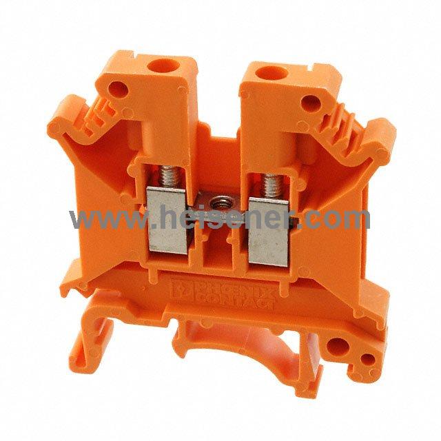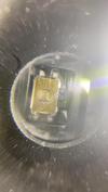
Part Number | T95R337M010CSSL |
---|---|
Manufacturer | Vishay Sprague |
Description | CAP TANT 330UF 10V 20% 2824 |
Datasheet | T95R337M010CSSL Datasheet |
Package | 2824 (7260 Metric) |
In Stock | 396 piece(s) |
Unit Price | $ 5.5584 * |
Lead Time | To be Confirmed |
Estimated Delivery Time | Jan 19 - Jan 24 (Choose Expedited Shipping) |
Request for Quotation |
|
Part Number # T95R337M010CSSL (Tantalum Capacitors) is manufactured by Vishay Sprague and distributed by Heisener. Being one of the leading electronics distributors, we carry many kinds of electronic components from some of the world’s top class manufacturers. Their quality is guaranteed by its stringent quality control to meet all required standards.
For T95R337M010CSSL specifications/configurations, quotation, lead time, payment terms of further enquiries please have no hesitation to contact us. To process your RFQ, please add T95R337M010CSSL with quantity into BOM. Heisener.com does NOT require any registration to request a quote of T95R337M010CSSL.
Manufacturer | Vishay Sprague |
Category | Capacitors - Tantalum Capacitors |
Datasheet | T95R337M010CSSLDatasheet |
Package | 2824 (7260 Metric) |
Series | TANTAMOUNT?, T95 |
Capacitance | 330µF |
Tolerance | ±20% |
Voltage - Rated | 10V |
Type | Conformal Coated |
ESR (Equivalent Series Resistance) | 45 mOhm |
Operating Temperature | -55°C ~ 125°C |
Lifetime @ Temp. | - |
Mounting Type | Surface Mount |
Package / Case | 2824 (7260 Metric) |
Size / Dimension | 0.283" L x 0.236" W (7.20mm x 6.00mm) |
Height - Seated (Max) | 0.150" (3.80mm) |
Lead Spacing | - |
Manufacturer Size Code | R |
Features | COTS (High Reliability) |
Failure Rate | - |
T95 www.vishay.com Vishay Sprague Revision: 17-Jul-2018 1 Document Number: 40081 For technical questions, contact: tantalum@vishay.com THIS DOCUMENT IS SUBJECT TO CHANGE WITHOUT NOTICE. THE PRODUCTS DESCRIBED HEREIN AND THIS DOCUMENT ARE SUBJECT TO SPECIFIC DISCLAIMERS, SET FORTH AT www.vishay.com/doc?91000 Solid Tantalum Chip Capacitors, TANTAMOUNT™, Hi-Rel COTS, Conformal Coated PERFORMANCE / ELECTRICAL CHARACTERISTICS www.vishay.com/doc?40209 Operating Temperature: -55 °C to +125 °C (above 85 °C, voltage derating is required) Capacitance Range: 0.15 μF to 680 μF Capacitance Tolerance: ± 20 %, ± 10 % standard Voltage Rating: 4 VDC to 50 VDC Moisture Sensitivity Level 2a FEATURES • High reliability; Weibull grading available • Surge current testing per MIL-PRF-55365 options available • Standard and low ESR options • Terminations: SnPb, standard, 100 % tin available • All cases except R case are halogen-free • Material categorization: for definitions of compliance please see www.vishay.com/doc?99912 Note * This datasheet provides information about parts that are RoHS-compliant and / or parts that are non RoHS-compliant. For example, parts with lead (Pb) terminations are not RoHS-compliant. Please see the information / tables in this datasheet for details Notes (1) Weibull 0.1 % and 0.01 % may not be available on all ratings. See detailed notes in ratings table or contact marketing for availability • We reserve the right to supply higher voltage ratings and tighter capacitance tolerance capacitors in the same case size • Low ESR solid tantalum chip capacitors allow delta ESR of 1.25 times the datasheet limits after mounting Available Available Available Available ORDERING INFORMATION T95 D 107 K 010 E A A S TYPE CASE CODE CAPACITANCE CAPACITANCE TOLERANCE DC VOLTAGE RATING AT +85 °C TERMINATION AND PACKAGING RELIABILITY LEVEL SURGE CURRENT ESR See Ratings and Case Codes table. This is expressed in picofarads. The first two digits are the significant figures. The third is the number of zeros to follow. K = ± 10 % M = ± 20 % This is expressed in volts. To complete the three-digit block, zeros precede the voltage rating. A decimal point is indicated by an “R” (6R3 = 6.3 V). Sn / Pb solder E = 7" (178 mm) reels L = 7" (178 mm) ½ reel 100 % tin C = 7" (178 mm) reels H = 7" (178 mm) ½ reel A = 1.0 % Weibull B = 0.1 % Weibull (1) C = 0.01 % Weibull (1) S = hi-rel standard burn-in Z = non-established reliability A = 10 cycles at +25 °C B = 10 cycles at -55 °C / +85 °C S = 3 cycles at +25 °C S = std. L = low DIMENSIONS in inches [millimeters] CASE CODE L (MAX.) W H A B D (REF.) J (MAX.) S 0.143 [3.63] 0.072 ± 0.008 [1.83 ± 0.20] 0.048 ± 0.008 [1.22 ± 0.20] 0.023 ± 0.010 [0.58 ± 0.25] 0.085 ± 0.015 [2.16 ± 0.37] 0.115 [2.9] 0.004 [0.10] V 0.143 [3.63] 0.104 ± 0.010 [2.65 ± 0.25] 0.051 ± 0.010 [1.30 ± 0.25] 0.023 ± 0.010 [0.58 ± 0.25] 0.085 ± 0.015 [2.16 ± 0.37] 0.115 [2.9] 0.004 [0.10] A 0.146 [3.7] 0.072 ± 0.012 [1.8 ± 0.3] 0.056 ± 0.012 [1.4 ± 0.3] 0.031 ± 0.012 [0.8 ± 0.3] 0.085 ± 0.016 [2.2 ± 0.40] 0.115 [2.9] 0.004 [0.10] B 0.158 [4.0] 0.110 + 0.012 / - 0.016 [2.8 + 0.3 / - 0.4] 0.075 + 0.012 / - 0.024 [1.9 + 0.3 / - 0.6] 0.031 ± 0.012 [0.8 ± 0.3] 0.097 ± 0.016 [2.5 ± 0.40] 0.138 [3.5] 0.004 [0.10] L A BD MAX. REF. W JJ H MAX. MAX. Tantalum wire nib identifies anode (+) terminal
T95 www.vishay.com Vishay Sprague Revision: 17-Jul-2018 2 Document Number: 40081 For technical questions, contact: tantalum@vishay.com THIS DOCUMENT IS SUBJECT TO CHANGE WITHOUT NOTICE. THE PRODUCTS DESCRIBED HEREIN AND THIS DOCUMENT ARE SUBJECT TO SPECIFIC DISCLAIMERS, SET FORTH AT www.vishay.com/doc?91000 Note • The anode termination (D less B) will be a minimum of 0.010" (0.25 mm) CASE CODE L (MAX.) W H A B D (REF.) J (MAX.) X 0.285 [7.24] 0.104 ± 0.010 [2.65 ± 0.25] 0.051 ± 0.010 [1.30 ± 0.25] 0.040 ± 0.020 [1.00 ± 0.50] 0.200 ± 0.027 [5.08 ± 0.69] 0.243 [6.2] 0.004 [0.10] Y 0.285 [7.24] 0.104 ± 0.010 [2.65 ± 0.25] 0.069 ± 0.010 [1.75 ± 0.25] 0.040 ± 0.020 [1.00 ± 0.50] 0.200 ± 0.027 [5.08 ± 0.69] 0.243 [6.2] 0.004 [0.10] Z 0.285 [7.24] 0.104 ± 0.010 [2.65 ± 0.25] 0.104 ± 0.010 [2.65 ± 0.25] 0.040 ± 0.020 [1.00 ± 0.50] 0.200 ± 0.027 [5.08 ± 0.69] 0.243 [6.2] 0.004 [0.10] C 0.281 [7.1] 0.126 ± 0.012 [3.2 ± 0.3] 0.098 ± 0.012 [2.5 ± 0.3] 0.051 ± 0.012 [1.3 ± 0.3] 0.180 ± 0.024 [4.6 ± 0.60] 0.236 [6.0] 0.004 [0.10] D 0.293 [7.4] 0.170 + 0.012 / - 0.024 [4.3 + 0.3 / - 0.6] 0.110 ± 0.012 [2.8 ± 0.3] 0.051 ± 0.012 [1.3 ± 0.3] 0.180 ± 0.024 [4.6 ± 0.60] 0.253 [6.4] 0.004 [0.10] R 0.283 [7.20] 0.235 + 0.012 / - 0.024 [6.0 + 0.30 / - 0.60] 0.136 + 0.012 / - 0.016 [3.50 + 0.30 / - 0.40] 0.051 ± 0.012 [1.30 ± 0.30] 0.180 ± 0.024 [4.60 ± 0.60] 0.243 [6.2] 0.004 [0.10] RATINGS AND CASE CODES μF 4 V 6.3 V 10 V 16 V 20 V 25 V 35 V 50 V 0.15 S 0.22 S 0.33 S S 0.47 S 0.68 S S 1.0 S S 1.5 S S V 2.2 S S V X 3.3 S S V 4.7 S S V X X Z / C 6.8 S S V A / X X Y Z C / D 10 S V X X Y C / Y Z R 15 V X B / X B / Y Z Z C / D / R R 22 X X Y B / Z Z R R 33 X Z Z D / R R 47 Y Y Z R D / R R 68 Y R D / R 100 Z Z R C / D R R 120 D / R R 150 D / R D R 180 R R 220 D / R D / R R 270 D 330 R C D / R R 390 R 470 D R 680 R R DIMENSIONS in inches [millimeters]
T95 www.vishay.com Vishay Sprague Revision: 17-Jul-2018 3 Document Number: 40081 For technical questions, contact: tantalum@vishay.com THIS DOCUMENT IS SUBJECT TO CHANGE WITHOUT NOTICE. THE PRODUCTS DESCRIBED HEREIN AND THIS DOCUMENT ARE SUBJECT TO SPECIFIC DISCLAIMERS, SET FORTH AT www.vishay.com/doc?91000 STANDARD RATINGS CAPACITANCE (μF) CASE CODE PART NUMBER MAX. DCL AT +25 °C (μA) MAX. DF AT +25 °C 120 Hz (%) STD. (S) MAX. ESR AT +25 °C 100 kHz () LOW (L) MAX. ESR AT +25 °C 100 kHz () AVAILABLE RELIABILITY LEVELS 4 VDC AT +85 °C; 2.7 VDC AT +125 °C 6.8 S T95S685(1)004(2)(3)(4)(5) 0.5 6 4.000 2.000 A, S, Z 10 S T95S106(1)004(2)(3)(4)(5) 0.5 6 4.000 2.000 A, S, Z 15 V T95V156(1)004(2)(3)(4)(5) 0.6 6 3.000 1.500 A, S, Z 22 X T95X226(1)004(2)(3)(4)(5) 0.9 6 2.000 1.000 A, S, Z 33 X T95X336(1)004(2)(3)(4)(5) 1.3 6 2.000 1.000 A, S, Z 47 Y T95Y476(1)004(2)(3)(4)(5) 1.9 6 1.200 0.600 A, S, Z 68 Y T95Y686(1)004(2)(3)(4)(5) 2.7 6 1.200 0.600 A, S, Z 100 Z T95Z107(1)004(2)(3)(4)(5) 4.0 6 0.800 0.400 A, S, Z 270 D T95D277(1)004(2)(3)(4)(5) 10.8 8 0.130 0.060 A, S, Z 330 R T95R337(1)004(2)(3)(4)(5) 13.2 8 0.130 0.080 A, S, Z 6.3 VDC AT +85 °C; 4 VDC AT +125 °C 4.7 S T95S475(1)6R3(2)(3)(4)(5) 0.5 6 4.000 2.000 A, S, Z 6.8 S T95S685(1)6R3(2)(3)(4)(5) 0.5 6 4.000 2.000 A, S, Z 10 V T95V106(1)6R3(2)(3)(4)(5) 0.6 6 3.000 1.500 A, S, Z 15 X T95X156(1)6R3(2)(3)(4)(5) 0.9 6 2.000 1.000 A, S, Z 22 X T95X226(1)6R3(2)(3)(4)(5) 1.4 6 2.000 1.000 A, S, Z 47 Y T95Y476(1)6R3(2)(3)(4)(5) 2.8 6 1.200 0.600 A, S, Z 100 Z T95Z107(1)6R3(2)(3)(4)(5) 6.0 6 0.800 0.400 A, S, Z 180 R T95R187(1)6R3(2)(3)(4)(5) 10.8 8 0.130 0.080 A, S, Z 220 D T95D227(1)6R3(2)(6)(4)(5) 13.9 8 0.140 0.065 A, B, S, Z 220 R T95R227(1)6R3(2)(3)(4)(5) 13.2 8 0.130 0.080 A, S, Z 330 C T95C337(1)6R3(2)(7)(4)(5) 20.8 8 0.170 0.080 A, B, C, S, Z 390 R T95R397(1)6R3(2)(3)(4)(5) 23.4 8 0.130 0.045 A, S, Z 470 D T95D477(1)6R3(2)(3)(4)(5) 28.2 10 0.130 0.060 A, S, Z 680 R T95R687(1)6R3(2)(3)(4)(5) 40.8 12 0.090 0.045 A, S, Z 10 VDC AT +85 °C; 7 VDC AT +125 °C 3.3 S T95S335(1)010(2)(3)(4)(5) 0.5 6 5.000 2.500 A, S, Z 4.7 S T95S475(1)010(2)(3)(4)(5) 0.5 6 4.000 2.000 A, S, Z 6.8 V T95V685(1)010(2)(3)(4)(5) 0.7 6 4.000 2.000 A, S, Z 10 X T95X106(1)010(2)(3)(4)(5) 1.0 6 3.000 1.500 A, S, Z 15 B T95B156(1)010(2)(6)(4)(5) 1.5 6 0.750 0.550 A, B, S, Z 15 X T95X156(1)010(2)(3)(4)(5) 1.5 6 2.000 1.000 A, S, Z 22 Y T95Y226(1)010(2)(6)(4)(5) 2.2 6 1.200 0.600 A, B, S, Z 33 Z T95Z336(1)010(2)(6)(4)(5) 3.3 6 0.800 0.400 A, B, S, Z 47 Z T95Z476(1)010(2)(3)(4)(5) 4.7 6 0.800 0.400 A, S, Z 100 R T95R107(1)010(2)(3)(4)(5) 10.0 8 0.140 0.075 A, S, Z 120 D T95D127(1)010(2)(7)(4)(5) 12.0 8 0.140 0.085 A, B, C, S, Z 120 R T95R127(1)010(2)(6)(4)(5) 12.0 8 0.140 0.070 A, B, S, Z Note • Part number definitions: (1) Capacitance tolerance: K, M (2) Termination and packaging: C, E, H, L (3) Reliability level: A, S, Z (4) Surge current: A, B, S (5) ESR: L, S (6) Reliability level: A, B, S, Z (7) Reliability level: A, B, C, S, Z
T95 www.vishay.com Vishay Sprague Revision: 17-Jul-2018 4 Document Number: 40081 For technical questions, contact: tantalum@vishay.com THIS DOCUMENT IS SUBJECT TO CHANGE WITHOUT NOTICE. THE PRODUCTS DESCRIBED HEREIN AND THIS DOCUMENT ARE SUBJECT TO SPECIFIC DISCLAIMERS, SET FORTH AT www.vishay.com/doc?91000 10 VDC AT +85 °C; 7 VDC AT +125 °C 150 D T95D157(1)010(2)(3)(4)(5) 15.0 8 0.140 0.075 A, S, Z 150 R T95R157(1)010(2)(3)(4)(5) 15.0 8 0.130 0.065 A, S, Z 220 D T95D227(1)010(2)(6)(4)(5) 22.0 8 0.140 0.065 A, B, S, Z 220 R T95R227(1)010(2)(3)(4)(5) 22.0 8 0.130 0.055 A, S, Z 330 D T95D337(1)010(2)(7)(4)(5) 33.0 8 0.140 0.065 A, B, C, S, Z 330 R T95R337(1)010(2)(6)(4)(5) 33.0 8 0.130 0.045 A, B, S, Z 470 R T95R477(1)010(2)(6)(4)(5) 47.0 14 0.120 0.060 A, B, S, Z 680 R T95R687(1)010(2)(6)(4)(5) 68.0 14 0.090 0.045 A, B, S, Z 16 VDC AT +85 °C; 10 VDC AT +125 °C 2.2 S T95S225(1)016(2)(3)(4)(5) 0.5 6 7.000 3.500 A, S, Z 3.3 S T95S335(1)016(2)(3)(4)(5) 0.5 6 5.000 2.500 A, S, Z 4.7 V T95V475(1)016(2)(3)(4)(5) 0.8 6 4.000 2.000 A, S, Z 6.8 A T95A685(1)016(2)(3)(4)(5) 1.1 6 2.800 0.800 A, S, Z 6.8 X T95X685(1)016(2)(3)(4)(5) 1.1 6 3.000 1.500 A, S, Z 10 X T95X106(1)016(2)(3)(4)(5) 1.6 6 3.000 1.500 A, S, Z 15 B T95B156(1)016(2)(3)(4)(5) 2.4 6 0.750 0.550 A, S, Z 15 Y T95Y156(1)016(2)(6)(4)(5) 2.4 6 1.200 0.600 A, B, S, Z 22 B T95B226(1)016(2)(6)(4)(5) 3.5 6 0.750 0.500 A, B, S, Z 22 Z T95Z226(1)016(2)(3)(4)(5) 3.5 6 0.800 0.400 A, S, Z 33 Z T95Z336(1)016(2)(3)(4)(5) 5.3 6 0.800 0.400 A, S, Z 68 R T95R686(1)016(2)(3)(4)(5) 10.9 6 0.600 0.095 A, S, Z 100 C T95C107(1)016(2)(6)(4)(5) 16.0 8 0.600 0.090 A, B, S, Z 100 D T95D107(1)016(2)(6)(4)(5) 16.0 8 0.140 0.080 A, B, S, Z 150 D T95D157(1)016(2)(6)(4)(5) 24.0 8 0.140 0.085 A, B, S, Z 180 R T95R187(1)016(2)(6)(4)(5) 28.8 8 0.130 0.055 A, B, S, Z 220 R T95R227(1)016(2)(6)(4)(5) 35.2 8 0.120 0.055 A, B, S, Z 330 R T95R337(1)016(2)(6)(4)(5) 52.8 14 0.110 0.055 A, B, S, Z 20 VDC AT +85 °C; 13 VDC AT +125 °C 1.5 S T95S155(1)020(2)(3)(4)(5) 0.5 6 7.000 3.500 A, S, Z 2.2 S T95S225(1)020(2)(3)(4)(5) 0.5 6 7.000 3.500 A, S, Z 3.3 V T95V335(1)020(2)(3)(4)(5) 0.7 6 6.000 3.000 A, S, Z 4.7 X T95X475(1)020(2)(3)(4)(5) 0.9 6 3.000 1.500 A, S, Z 6.8 X T95X685(1)020(2)(3)(4)(5) 1.4 6 3.000 1.500 A, S, Z 10 Y T95Y106(1)020(2)(3)(4)(5) 2.0 6 2.000 1.000 A, S, Z 15 Z T95Z156(1)020(2)(3)(4)(5) 3.0 6 1.200 0.600 A, S, Z 22 Z T95Z226(1)020(2)(3)(4)(5) 4.4 6 0.800 0.400 A, S, Z 47 R T95R476(1)020(2)(3)(4)(5) 9.4 6 0.200 0.110 A, S, Z 100 R T95R107(1)020(2)(6)(4)(5) 20.0 8 0.140 0.090 A, B, S, Z 120 R T95R127(1)020(2)(6)(4)(5) 24.0 8 0.140 0.080 A, B, S, Z 150 R T95R157(1)020(2)(6)(4)(5) 30.0 8 0.140 0.075 A, B, S, Z STANDARD RATINGS CAPACITANCE (μF) CASE CODE PART NUMBER MAX. DCL AT +25 °C (μA) MAX. DF AT +25 °C 120 Hz (%) STD. (S) MAX. ESR AT +25 °C 100 kHz () LOW (L) MAX. ESR AT +25 °C 100 kHz () AVAILABLE RELIABILITY LEVELS Note • Part number definitions: (1) Capacitance tolerance: K, M (2) Termination and packaging: C, E, H, L (3) Reliability level: A, S, Z (4) Surge current: A, B, S (5) ESR: L, S (6) Reliability level: A, B, S, Z (7) Reliability level: A, B, C, S, Z
T95 www.vishay.com Vishay Sprague Revision: 17-Jul-2018 5 Document Number: 40081 For technical questions, contact: tantalum@vishay.com THIS DOCUMENT IS SUBJECT TO CHANGE WITHOUT NOTICE. THE PRODUCTS DESCRIBED HEREIN AND THIS DOCUMENT ARE SUBJECT TO SPECIFIC DISCLAIMERS, SET FORTH AT www.vishay.com/doc?91000 25 VDC AT +85 °C; 17 VDC AT +125 °C 0.68 S T95S684(1)025(2)(3)(4)(5) 0.5 4 10.000 5.000 A, S, Z 1.0 S T95S105(1)025(2)(3)(4)(5) 0.5 4 7.000 3.500 A, S, Z 1.5 S T95S155(1)025(2)(3)(4)(5) 0.5 6 7.000 3.500 A, S, Z 2.2 V T95V225(1)025(2)(3)(4)(5) 0.6 6 4.000 2.000 A, S, Z 4.7 X T95X475(1)025(2)(3)(4)(5) 1.2 6 3.000 1.500 A, S, Z 6.8 Y T95Y685(1)025(2)(3)(4)(5) 1.7 6 2.000 1.000 A, S, Z 10 C T95C106(1)025(2)(6)(4)(5) 2.5 6 0.570 0.280 A, B, S, Z 10 Y T95Y106(1)025(2)(3)(4)(5) 2.5 6 2.000 1.000 A, S, Z 15 Z T95Z156(1)025(2)(3)(4)(5) 3.8 6 1.200 0.600 A, S, Z 33 D T95D336(1)025(2)(6)(4)(5) 8.3 6 0.260 0.130 A, B, S, Z 33 R T95R336(1)025(2)(6)(4)(5) 8.3 6 0.250 0.130 A, B, S, Z 47 D T95D476(1)025(2)(6)(4)(5) 11.8 6 0.260 0.130 A, B, S, Z 47 R T95R476(1)025(2)(3)(4)(5) 11.8 6 0.200 0.108 A, S, Z 68 D T95D686(1)025(2)(6)(4)(5) 17.0 8 0.260 0.200 A, B, S, Z 68 R T95R686(1)025(2)(6)(4)(5) 17.0 6 0.200 0.095 A, B, S, Z 100 R T95R107(1)025(2)(6)(4)(5) 25.0 8 0.200 0.090 A, B, S, Z 35 VDC AT +85 °C; 23 VDC AT +125 °C 0.15 S T95S154(1)035(2)(3)(4)(5) 0.5 4 36.000 18.000 A, S, Z 0.22 S T95S224(1)035(2)(3)(4)(5) 0.5 4 30.000 15.000 A, S, Z 0.33 S T95S334(1)035(2)(3)(4)(5) 0.5 4 24.000 12.000 A, S, Z 0.47 S T95S474(1)035(2)(3)(4)(5) 0.5 4 18.000 9.000 A, S, Z 0.68 S T95S684(1)035(2)(3)(4)(5) 0.5 4 10.000 5.000 A, S, Z 1.0 S T95S105(1)035(2)(3)(4)(5) 0.5 4 7.000 3.500 A, S, Z 1.5 V T95V155(1)035(2)(3)(4)(5) 0.5 6 6.000 3.000 A, S, Z 2.2 X T95X225(1)035(2)(3)(4)(5) 0.8 6 4.000 2.000 A, S, Z 6.8 Z T95Z685(1)035(2)(6)(4)(5) 2.4 6 1.600 0.800 A, B, S, Z 10 Z T95Z106(1)035(2)(3)(4)(5) 3.5 6 1.200 0.600 A, S, Z 15 C T95C156(1)035(2)(6)(4)(5) 5.3 6 0.600 0.400 A, B, S, Z 15 D T95D156(1)035(2)(3)(4)(5) 5.3 6 0.410 0.270 A, S, Z 15 R T95R156(1)035(2)(3)(4)(5) 5.3 6 0.380 0.190 A, S, Z 22 R T95R226(1)035(2)(3)(4)(5) 7.7 6 0.280 0.240 A, S, Z 33 R T95R336(1)035(2)(6)(4)(5) 11.6 6 0.280 0.200 A, B, S, Z 47 R T95R476(1)035(2)(6)(4)(5) 16.5 6 0.280 0.200 A, B, S, Z 50 VDC AT +85 °C; 33 VDC AT +125 °C 0.33 S T95S334(1)050(2)(6)(4)(5) 0.5 4 20.000 10.000 A, B, S, Z 4.7 Z T95Z475(1)050(2)(3)(4)(5) 2.4 6 0.800 0.600 A, S, Z 4.7 C T95C475(1)050(2)(6)(4)(5) 2.4 6 1.400 0.800 A, B, S, Z 6.8 C T95C685(1)050(2)(6)(4)(5) 3.4 6 1.300 0.700 A, B, S, Z 6.8 D T95D685(1)050(2)(6)(4)(5) 3.4 6 0.820 0.450 A, B, S, Z 10 R T95R106(1)050(2)(6)(4)(5) 5.0 6 0.650 0.500 A, B, S, Z 15 R T95R156(1)050(2)(3)(4)(5) 7.5 6 0.400 0.350 A, S, Z 22 R T95R226(1)050(2)(3)(4)(5) 11.0 6 0.390 0.300 A, S, Z STANDARD RATINGS CAPACITANCE (μF) CASE CODE PART NUMBER MAX. DCL AT +25 °C (μA) MAX. DF AT +25 °C 120 Hz (%) STD. (S) MAX. ESR AT +25 °C 100 kHz () LOW (L) MAX. ESR AT +25 °C 100 kHz () AVAILABLE RELIABILITY LEVELS Note • Part number definitions: (1) Capacitance tolerance: K, M (2) Termination and packaging: C, E, H, L (3) Reliability level: A, S, Z (4) Surge current: A, B, S (5) ESR: L, S (6) Reliability level: A, B, S, Z (7) Reliability level: A, B, C, S, Z
T95 www.vishay.com Vishay Sprague Revision: 17-Jul-2018 6 Document Number: 40081 For technical questions, contact: tantalum@vishay.com THIS DOCUMENT IS SUBJECT TO CHANGE WITHOUT NOTICE. THE PRODUCTS DESCRIBED HEREIN AND THIS DOCUMENT ARE SUBJECT TO SPECIFIC DISCLAIMERS, SET FORTH AT www.vishay.com/doc?91000 POWER DISSIPATION CASE CODE MAXIMUM PERMISSIBLE POWER DISSIPATION AT +25 °C (W) IN FREE AIR A 0.075 B 0.085 C 0.110 D 0.150 R 0.250 S 0.080 V 0.095 X 0.110 Y 0.120 Z 0.135 STANDARD PACKAGING QUANTITY CASE CODE UNITS PER REEL 7" FULL REEL 7" HALF REEL A 2000 1000 B 2000 1000 C 500 250 D 500 250 R 600 300 S 2500 1250 V 2500 1250 X 2000 1000 Y 1500 750 Z 1500 750 PRODUCT INFORMATION Conformal Coated Guide www.vishay.com/doc?40150Pad Dimensions Packaging Dimensions Moisture Sensitivity (MSL) www.vishay.com/doc?40135 SELECTOR GUIDES Solid Tantalum Selector Guide www.vishay.com/doc?49053 Solid Tantalum Chip Capacitors www.vishay.com/doc?40091 FAQ Frequently Asked Questions www.vishay.com/doc?40110
Conformal Coated Guide www.vishay.com Vishay Sprague Revision: 11-Oct-2018 1 Document Number: 40150 For technical questions, contact: tantalum@vishay.com THIS DOCUMENT IS SUBJECT TO CHANGE WITHOUT NOTICE. THE PRODUCTS DESCRIBED HEREIN AND THIS DOCUMENT ARE SUBJECT TO SPECIFIC DISCLAIMERS, SET FORTH AT www.vishay.com/doc?91000 Guide for Conformal Coated Tantalum Capacitors INTRODUCTION Tantalum electrolytic capacitors are the preferred choice in applications where volumetric efficiency, stable electrical parameters, high reliability, and long service life are primary considerations. The stability and resistance to elevated temperatures of the tantalum / tantalum oxide / manganese dioxide system make solid tantalum capacitors an appropriate choice for today's surface mount assembly technology. Vishay Sprague has been a pioneer and leader in this field, producing a large variety of tantalum capacitor types for consumer, industrial, automotive, military, and aerospace electronic applications. Tantalum is not found in its pure state. Rather, it is commonly found in a number of oxide minerals, often in combination with Columbium ore. This combination is known as “tantalite” when its contents are more than one-half tantalum. Important sources of tantalite include Australia, Brazil, Canada, China, and several African countries. Synthetic tantalite concentrates produced from tin slags in Thailand, Malaysia, and Brazil are also a significant raw material for tantalum production. Electronic applications, and particularly capacitors, consume the largest share of world tantalum production. Other important applications for tantalum include cutting tools (tantalum carbide), high temperature super alloys, chemical processing equipment, medical implants, and military ordnance. Vishay Sprague is a major user of tantalum materials in the form of powder and wire for capacitor elements and rod and sheet for high temperature vacuum processing. THE BASICS OF TANTALUM CAPACITORS Most metals form crystalline oxides which are non-protecting, such as rust on iron or black oxide on copper. A few metals form dense, stable, tightly adhering, electrically insulating oxides. These are the so-called “valve” metals and include titanium, zirconium, niobium, tantalum, hafnium, and aluminum. Only a few of these permit the accurate control of oxide thickness by electrochemical means. Of these, the most valuable for the electronics industry are aluminum and tantalum. Capacitors are basic to all kinds of electrical equipment, from radios and television sets to missile controls and automobile ignitions. Their function is to store an electrical charge for later use. Capacitors consist of two conducting surfaces, usually metal plates, whose function is to conduct electricity. They are separated by an insulating material or dielectric. The dielectric used in all tantalum electrolytic capacitors is tantalum pentoxide. Tantalum pentoxide compound possesses high-dielectric strength and a high-dielectric constant. As capacitors are being manufactured, a film of tantalum pentoxide is applied to their electrodes by means of an electrolytic process. The film is applied in various thicknesses and at various voltages and although transparent to begin with, it takes on different colors as light refracts through it. This coloring occurs on the tantalum electrodes of all types of tantalum capacitors. Rating for rating, tantalum capacitors tend to have as much as three times better capacitance / volume efficiency than aluminum electrolytic capacitors. An approximation of the capacitance / volume efficiency of other types of capacitors may be inferred from the following table, which shows the dielectric constant ranges of the various materials used in each type. Note that tantalum pentoxide has a dielectric constant of 26, some three times greater than that of aluminum oxide. This, in addition to the fact that extremely thin films can be deposited during the electrolytic process mentioned earlier, makes the tantalum capacitor extremely efficient with respect to the number of microfarads available per unit volume. The capacitance of any capacitor is determined by the surface area of the two conducting plates, the distance between the plates, and the dielectric constant of the insulating material between the plates. In the tantalum electrolytic capacitor, the distance between the plates is very small since it is only the thickness of the tantalum pentoxide film. As the dielectric constant of the tantalum pentoxide is high, the capacitance of a tantalum capacitor is high if the area of the plates is large: where C = capacitance e = dielectric constant A = surface area of the dielectric t = thickness of the dielectric Tantalum capacitors contain either liquid or solid electrolytes. In solid electrolyte capacitors, a dry material (manganese dioxide) forms the cathode plate. A tantalum lead is embedded in or welded to the pellet, which is in turn connected to a termination or lead wire. The drawings show the construction details of the surface mount types of tantalum capacitors shown in this catalog. COMPARISON OF CAPACITOR DIELECTRIC CONSTANTS DIELECTRIC e DIELECTRIC CONSTANT Air or vacuum 1.0 Paper 2.0 to 6.0 Plastic 2.1 to 6.0 Mineral oil 2.2 to 2.3 Silicone oil 2.7 to 2.8 Quartz 3.8 to 4.4 Glass 4.8 to 8.0 Porcelain 5.1 to 5.9 Mica 5.4 to 8.7 Aluminum oxide 8.4 Tantalum pentoxide 26 Ceramic 12 to 400K C eA t ------=
Conformal Coated Guide www.vishay.com Vishay Sprague Revision: 11-Oct-2018 2 Document Number: 40150 For technical questions, contact: tantalum@vishay.com THIS DOCUMENT IS SUBJECT TO CHANGE WITHOUT NOTICE. THE PRODUCTS DESCRIBED HEREIN AND THIS DOCUMENT ARE SUBJECT TO SPECIFIC DISCLAIMERS, SET FORTH AT www.vishay.com/doc?91000 SOLID ELECTROLYTE TANTALUM CAPACITORS Solid electrolyte capacitors contain manganese dioxide, which is formed on the tantalum pentoxide dielectric layer by impregnating the pellet with a solution of manganous nitrate. The pellet is then heated in an oven, and the manganous nitrate is converted to manganese dioxide. The pellet is next coated with graphite, followed by a layer of metallic silver, which provides a conductive surface between the pellet and the can in which it will be enclosed. After assembly, the capacitors are tested and inspected to assure long life and reliability. It offers excellent reliability and high stability for consumer and commercial electronics with the added feature of low cost. Surface mount designs of “Solid Tantalum” capacitors use lead frames or lead frameless designs as shown in the accompanying drawings. TANTALUM CAPACITORS FOR ALL DESIGN CONSIDERATIONS Solid electrolyte designs are the least expensive for a given rating and are used in many applications where their very small size for a given unit of capacitance is of importance. They will typically withstand up to about 10 % of the rated DC working voltage in a reverse direction. Also important are their good low temperature performance characteristics and freedom from corrosive electrolytes. Vishay Sprague patented the original solid electrolyte capacitors and was the first to market them in 1956. Vishay Sprague has the broadest line of tantalum capacitors and has continued its position of leadership in this field. Data sheets covering the various types and styles of Vishay Sprague capacitors for consumer and entertainment electronics, industry, and military applications are available where detailed performance characteristics must be specified. TYPE 195D, 572D, 591D, 592D / W, 594D, 595D, 695D, T95, 14002 TYPE 597D / T97 / 13008 Cathode Termination (Silver + Ni/Sn/Plating) Encapsulation Anode Termination (Silver + Ni/Sn/Plating) Sintered Tantalum Pellet MnO2 /Carbon/Silver Coating Sponge Teflon/Epoxy Tower Cathode Termination (Silver + Ni/Sn/Plating) Encapsulation Anode Termination (Silver + Ni/Sn/Plating) Sponge Teflon/Epoxy Tower Sintered Tantalum Pellet MnO2/Carbon/Silver Coating Silver Epoxy TYPE 194D TYPE T96 TYPE T98 Encapsulation SnPb or Gold Plated Ni Anode End Cap Termination Sponge Teflon Anode BackfillMnO2/Carbon/ Silver Coating Sintered Tantalum Pellet Conductive Silver Epoxy Adhesive Cathode Backfill SnPb or Gold Plated Ni Cathode End Cap Termination Cathode Termination (Silver + Ni/Sn or Ni/SnPb Plating) Encapsulation Anode Termination (Silver + Ni/Sn or Ni/SnPb Plating) Epoxy Tower/ Sponge Teflon Sintered Tantalum Pellet MnO2/Carbon/ Silver Coating Intermediate Cathode Silver Fuse Cathode Termination (Silver + Ni/Sn or Ni/SnPb Plating) Encapsulation Anode Termination (Silver + Ni/Sn or Ni/SnPb Plating) Epoxy Tower/ Sponge Teflon Sintered Tantalum Pellet MnO2/Carbon/ Silver Coating Intermediate Cathode Silver Fuse
Conformal Coated Guide www.vishay.com Vishay Sprague Revision: 11-Oct-2018 3 Document Number: 40150 For technical questions, contact: tantalum@vishay.com THIS DOCUMENT IS SUBJECT TO CHANGE WITHOUT NOTICE. THE PRODUCTS DESCRIBED HEREIN AND THIS DOCUMENT ARE SUBJECT TO SPECIFIC DISCLAIMERS, SET FORTH AT www.vishay.com/doc?91000 COMMERCIAL PRODUCTS SOLID TANTALUM CAPACITORS - CONFORMAL COATED SERIES 592W 592D 591D 595D 594D PRODUCT IMAGE TYPE Surface mount TANTAMOUNT™ chip, conformal coated FEATURES Low profile, robust design for use in pulsed applications Low profile, maximum CV Low profile, low ESR, maximum CV Maximum CV Low ESR, maximum CV TEMPERATURE RANGE -55 °C to +125 °C (above 40 °C, voltage deratig is required) -55 °C to +125 °C (above 85 °C, voltage derating is required) CAPACITANCE RANGE 330 μF to 2200 μF 1 μF to 2200 μF 1 μF to 1500 μF 0.1 μF to 1500 μF 1 μF to 1500 μF VOLTAGE RANGE 6 V to 10 V 4 V to 50 V 4 V to 50 V 4 V to 50 V 4 V to 50 V CAPACITANCE TOLERANCE ± 20 % ± 10 %, ± 20 % ± 10 %, ± 20 % ± 10 %, ± 20 % ± 10 %, ± 20 % LEAKAGE CURRENT 0.01 CV or 0.5 μA, whichever is greater DISSIPATION FACTOR 14 % to 45 % 4 % to 50 % 4 % to 50 % 4 % to 20 % 4 % to 20 % CASE CODES C, M, X S, A, B, C, D, R, M, X A, B, C, D, R, M T, S, A, B, C, D, G, M, R B, C, D, R TERMINATION 100 % matte tin 100 % matte tin standard, tin / lead and gold plated available SOLID TANTALUM CAPACITORS - CONFORMAL COATED SERIES 597D 572D 695D 195D 194D PRODUCT IMAGE TYPE TANTAMOUNT™ chip, conformal coated FEATURES Ultra low ESR, maximum CV, multi-anode Low profile, maximum CV Pad compatible with 194D and CWR06 US and European case sizes Industrial version of CWR06 / CWR16 TEMPERATURE RANGE -55 °C to +125 °C (above 85 °C, voltage derating is required) CAPACITANCE RANGE 10 μF to 2200 μF 2.2 μF to 220 μF 0.1 μF to 270 μF 0.1 μF to 330 μF 0.1 μF to 330 μF VOLTAGE RANGE 4 V to 75 V 4 V to 35 V 4 V to 50 V 2 V to 50 V 4 V to 50 V CAPACITANCE TOLERANCE ± 10 %, ± 20 % LEAKAGE CURRENT 0.01 CV or 0.5 μA, whichever is greater DISSIPATION FACTOR 6 % to 20 % 6 % to 26 % 4 % to 8 % 4 % to 8 % 4 % to 10 % CASE CODES V, D, E, R, F, Z, M, H P, Q, S, A, B, T A, B, D, E, F, G, H C, S, V, X, Y, Z, R, A, B, D, E, F, G, H A, B, C, D, E, F, G, H TERMINATION 100 % matte tin standard, tin / lead solder plated available 100 % matte tin standard, gold plated available 100 % matte tin standard, tin / lead and gold plated available Gold plated standard; tin / lead solder plated and hot solder dipped available
Coll*****Boyer
December 25, 2020
We guarantee 100% customer satisfaction.
Our experienced sales team and tech support team back our services to satisfy all our customers.
We provide 90 days warranty.
If the items you received were not in perfect quality, we would be responsible for your refund or replacement, but the items must be returned in their original condition.
Payment Methods | |
Delivery Services |
Heisener's commitment to quality has shaped our processes for sourcing, testing, shipping, and every step in between. This foundation underlies each component we sell.