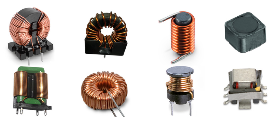
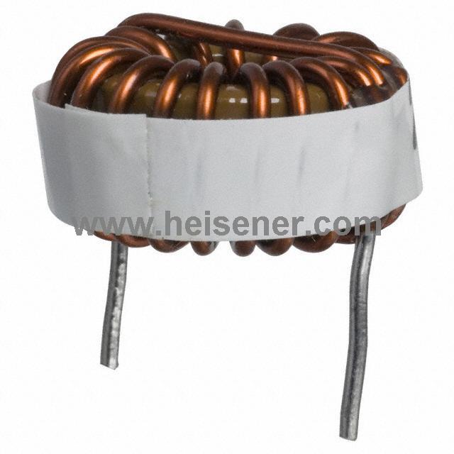
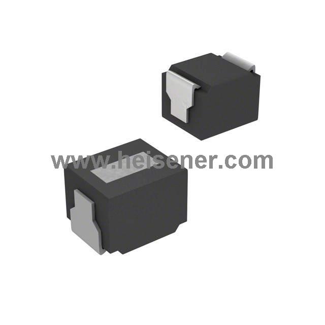
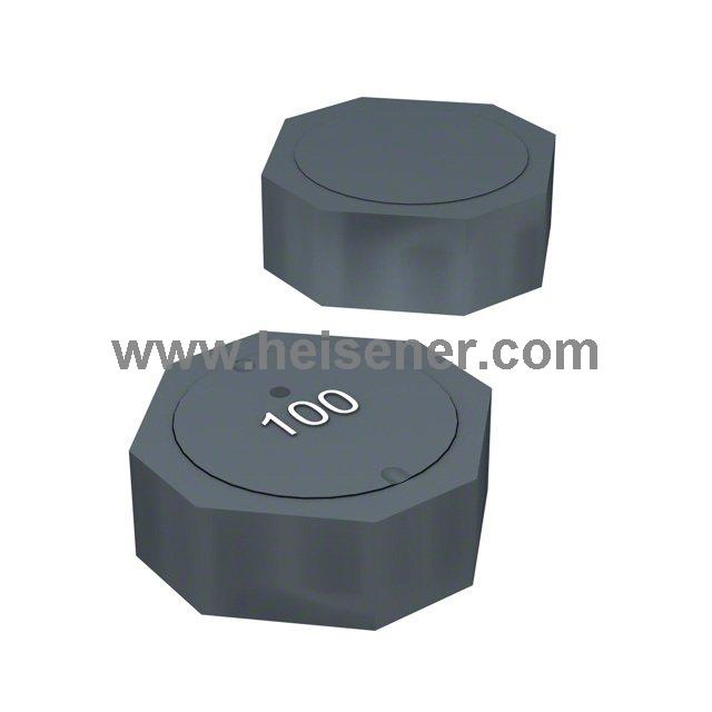
An inductor is an electromagnetic component made by winding a certain number of insulated wire turns around a coil frame or magnetic core. It is also known as a choke or reactor.
This article provides a detailed guide to inductors, including their definition, working principle, structure, symbol, inductance value, and more.
Symbol and Working Principle of Inductors
An inductor is one of the three basic passive components in electronics. Its main function is to store electrical energy in the form of a magnetic field.
Let’s take a cylindrical coil as an example to explain the basic working principle of an inductor:

As shown in the figure above, when a constant current flows through the coil, a steady magnetic field is formed around it according to the right-hand rule. When alternating current flows through the coil, the magnetic field also changes. A changing magnetic field creates an electric field, which produces an induced voltage and current in the coil. The direction of this induced current always tries to resist the change in the original magnetic field. Since the changing magnetic field is caused by the alternating current, the inductor works against any change in current in an AC circuit.
- When the current increases, the magnetic field becomes stronger. The direction of the magnetic field change is the same as the original one. According to the left-hand rule, the induced current flows in the opposite direction of the original current, which makes the total current smaller.
- When the current decreases, the magnetic field becomes weaker. The direction of the magnetic field change is opposite to the original one. The induced current now flows in the same direction as the original current, making the total current larger.
This is known as Lenz’s Law. In short, an inductor resists changes in the current flowing through it. It offers higher impedance to alternating current. For the same inductor, the faster the current changes, the larger the induced current will be, and the higher the impedance will become. Similarly, if the inductance value is larger, it will produce a greater induced current under the same current change, leading to higher impedance.
Key Parameters of Inductors
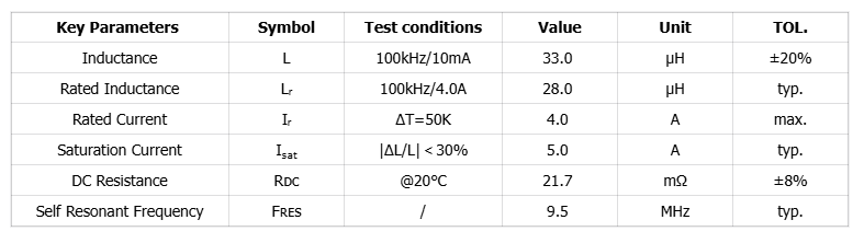
L/LR
The inductance depends on the number of turns, the winding method, and whether a magnetic core is used and what material it is made of. Its unit is Henry (H). When the current changes by 1A per second and produces 1V of induced voltage, the inductance is 1H.
In the parameters, L is measured at 100kHz/10mA with a very small DC bias. LR is measured at 100kHz and 4.0A rated current. The inductance value is slightly lower because of the magnetic core material. The tolerance of this inductor is ±20%, and the common tolerance is ±20% or ±30%.
IR
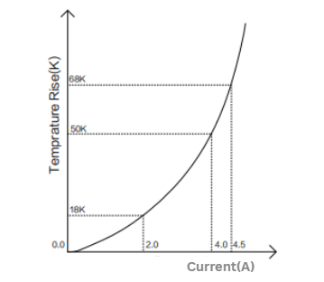
Rated current limits how much the inductor’s temperature can rise. In the chart, “ΔT = 50K” shows the current when the temperature rises by 50K. As shown below, this current is 4.0A, which is the rated/temperature rise current of the inductor (T(K) = T(C) + 273.15). The rated/temperature rise current is the continuous DC current the inductor can carry. It mainly depends on the wire diameter of the copper winding (larger diameter allows higher current) and the inductor’s heat dissipation ability.
ISAT
Saturation current is the current that makes an inductor enter magnetic saturation. At this point, the inductance drops by a certain percentage (usually 30%–50%), and the current rises further. As shown in the Figure 4, a 33 μH inductor has an inductance of 21 μH (36.4% drop) when the current reaches the saturation current of 5.0 A. Usually, the rated current of an inductor is the smaller value between the rated/temperature rise current and the saturation current. In use, the inductor current should be kept below these values with some margin.
RDC
DC resistance describes the resistance of an inductor when current and magnetic fields are stable. Ideally, the inductor acts like a short circuit, but in reality, it has milliohm-level resistance. RDC mainly affects heat loss, so lower DC resistance means less loss.
Fres
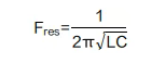
The capacitance between turns of the coil, between the coil and the shield, and between the coil and the base is called parasitic capacitance. This capacitance gives the coil a natural or resonant frequency (Fres), which is:
Structure and Value of Inductors
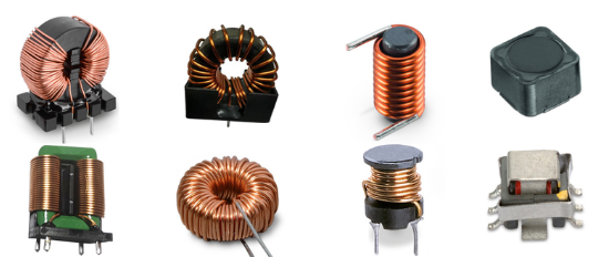
The most basic inductor is made by winding a wire into a coil, with the two ends of the wire as external terminals. In recent years, most inductors have been made by winding the wire around a magnetic core.
The inductance of an inductor can be calculated using the following formula:
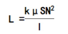
L: Inductance (H)
k: Nagao coefficient
μ: Permeability of the core (H/m)
N: Number of turns of the coil
S: Cross-sectional area of the coil (m²)
l: Length of the coil (m)
From this formula, we can see that the inductance increases by
1) enlarging the cross-sectional area S
2) increasing the number of turns N
3) inserting a core to increase the permeability µ
Inductor vs. Capacitor
Inductors in circuits mainly work for filtering, oscillating, delaying, and notch functions. They also help select signals, filter noise, stabilize current, and reduce electromagnetic interference.
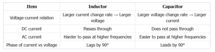
The most common use of an inductor is in an LC filter circuit with a capacitor. A capacitor “blocks DC and passes AC,” while an inductor “passes DC and blocks AC.”
Comparing the features of inductors and capacitors, the table below shows that inductors have opposite characteristics to capacitors.
Inductors and Impedance Matching
Impedance matching usually means matching the impedance of the power source with the impedance of the load. When the load impedance equals the source impedance, maximum power is transferred, improving circuit efficiency. If the load is capacitive to the source, an inductor can be added to cancel the load capacitance and achieve impedance matching.
The absolute value of impedance is:
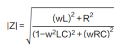
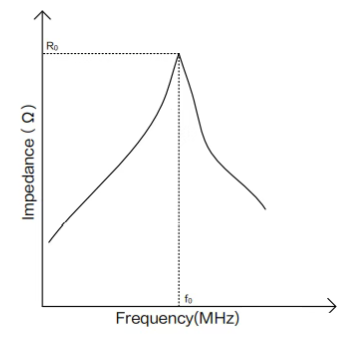
As shown in Figure 7, left of the resonant frequency, the inductor dominates, and impedance rises with increasing frequency, showing mainly inductive behavior. At the resonant frequency, impedance reaches its maximum. Right of the resonant frequency, the capacitor dominates, and impedance decreases with increasing frequency, showing mainly capacitive behavior.
Energy Stored
When current flows through an inductor, energy is stored in its magnetic field. When the current in the inductor increases and di/dt > 0, the instantaneous power P > 0, which is positive, meaning the inductor is absorbing energy.
Conversely, when the current decreases and di/dt < 0, the instantaneous power P < 0, which is negative, meaning the inductor is releasing energy back to the circuit. By integrating this power equation, the total magnetic energy stored in the inductor (always positive) can be calculated as follows:
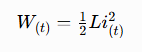
W: joules
L: Henries
i: Amperes
Electric energy is actually stored in the magnetic field around an inductor when current flows through it. In an ideal inductor with no resistance or capacitance, energy enters the inductor without loss and is stored in the magnetic field as the current increases. When the current decreases and the magnetic field collapses, the energy is released back to the circuit.
In an AC circuit, an inductor continuously stores and releases energy in each cycle. If the current is constant like in a DC circuit, the stored energy does not change because P = L i (di/dt) = 0. Therefore, an inductor is defined as a passive component. It can store energy and release it to the circuit but cannot generate energy. An ideal inductor is a “lossless” component and can store energy indefinitely without loss.
However, real inductors always have resistance in the coil windings. Whether the current is AC or DC, as long as it flows through the resistance, energy is lost as heat according to Ohm’s law: P = I²R.
 0
0







 Login/Register
 BOM
BOM
 Cart
Cart