The functions of 5G connection and 4K ultra-high-definition display currently possessed by mobile terminals are often "big power consumers", far exceeding the energy storage of conventional dual-cell batteries. In the face of these high-power applications or devices, USB (PD) fast charging can quickly replenish power sources for terminals with efficient charging capabilities. However, it is not easy for designers to adopt the USB PD protocol standard, often requiring complex firmware development and additional hardware design. For example, the short distance between the pins of the Type-C port and the high voltage (20V) can often cause damage if the connector is inserted or disconnected at the wrong angle. In fact, the USB Type-C and USB PD specifications require designers to have software and hardware design skills, as well as a deep understanding of the USB specification.
As consumer electronic devices such as cameras, AR/VR systems, and wireless speakers gradually lead the development of USB Type-C and USB PD technologies, how to speed up the product launch process and shorten the development cycle? How to expand the wide application of USB Type-C and USB PD technology in industrial and medical fields? Below ADI will share some tips for simplifying USB PD design to help you do more with less.
Analysis of Design Challenges of USB-C Charging System
USB Type-C and USB PD provide a symmetrical 24-pin interface specification for data transfer and power supply, enabling designers to design and implement a common interface. USB-C can provide 5V/up to 3A charging current (15W), while USB PD 3.0 can provide 5V to 20V/up to 5A supply current (100W). To design a USB-C charging system, consider the following challenges:
• Resolve signal integrity and speed issues
• Interfacing with various legacy interfaces
• Ensure that the design can be used for a wide voltage and current range, including support for cold cranking (0V until end-to-end detection is completed)
• Make sure the charger and port controller can communicate with each other when plugged into USB-C power
• Meet the small size requirements of consumer devices
• Maintain thermal efficiency and minimize temperature rise
To address these challenges, designers typically develop complex host-side software for the USB-C protocol, or add additional components such as external FETs and external microcontrollers. However, some charging system solutions that fully comply with the protocol can greatly simplify the design implementation. Other solutions are designed with event-based action scripts to make the customization process easier. At the same time, highly integrated ICs will also reduce the use of a large number of discrete components. In addition, designers need to consider the ability to maintain reliable operation in harsh environments, such as varying temperatures or humidity.
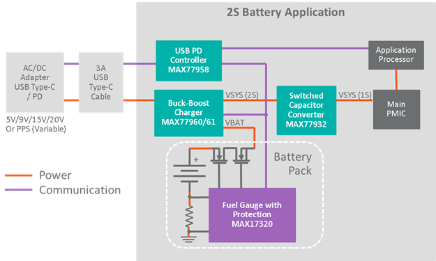
Another factor that must be considered is the use of high-capacity batteries, which are required for power-hungry end devices to sustain longer runtimes. Compared with the 1S battery, the 2S battery can increase the capacity without increasing the charging current. Since USB-C supports input voltages between 5V and 20V, and 2S or 3S batteries are in between, a buck-boost converter can bridge the gap.The following figure shows the schematic flow chart of the application based on 2S battery.
Out-of-the-box USB-C compatibility
ADI's new USB-C charging system solution complies with the USB PD 3.0 specification, eliminates the need for firmware development, and works out of the box, reducing development time by three months. Its compact size reduces the size of the solution in half compared to similar solutions. The MAX77958 USB Type-C and USB PD charge controllers require no additional firmware development, thanks to GUI-driven custom scripts, BC1.2 protocol support, and integration with Fast Role Switch (FRS), Dual Role Port (DRP) Configuration settings related to Try.SNK mode. This standalone product eliminates the need for an external microcontroller and provides out-of-the-box USB PD 3.0 compatibility, enabling users to define the functionality of their end application without the need to develop firmware. The product also features 28V rated voltage, CC pin short-to-VBUS short-circuit protection, integrated analog-to-digital converter (ADC), and humidity detection/corrosion protection, making it suitable for all kinds of harsh working environments.
The MAX77958 can autonomously control the companion charger through its main I2C interface. The MAX77961 is a 6A buck-boost charger with integrated FETs for fast charging of high-capacity 2S and 3S Li-Ion batteries. It offers a wide input voltage range (3.5V to 25V) for USB PD charging, does not require discrete FETs, and is configurable with or without an external processor. Its peak efficiency is 97% at an input voltage of 9VIN, an output voltage of 7.4VOUT, and an output current of 1.5AOUT.
Interested parties can use the MAX77958EVKIT-2S6# (for 2S batteries) or the MAX77958EVKIT-3S6# (for 3S batteries) to evaluate both devices. These two devices demonstrate how the MAX77958 uses I2C to control the MAX77961 charger.
The above ADI devices belong to the generalized USB Type-C and USB PD device series. The series includes a variety of products such as high-efficiency chargers and converters, durable automatic controllers, power paths and protection ICs, which can be freely selected and combined.