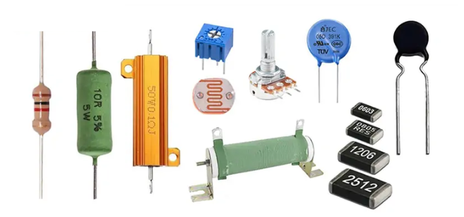
A variable resistor is an essential electronic component widely used for adjusting current, voltage, or signal levels in a circuit. Unlike fixed resistors, variable resistors allow users to fine-tune electrical parameters, so they are suitable for more flexible applications.
In this blog, Heisener Electronics will provide a comprehensive guide of variable resistors for engineers, students, and electronics enthusiasts with a clear understanding of variable resistors, including their definition, working principles, practical applications, and more. We aim to help readers make informed choices when selecting this component.
What is a Resistor?
A resistor is a current-limiting component. When a resistor is connected to a circuit, its resistance value is fixed and it typically has two leads. It can limit the amount of current flowing through the branch it's connected to. Resistors are generally represented by the letter R, and their unit is the ohm (Ω)Real-world components like light bulbs and heating filaments can also be represented as resistor elements.
Most people are familiar with Ohm's Law: V=IR. In this formula, R stands for resistance. V is the voltage across the resistor, and I is the current flowing through it. This equation connects the fundamental working principles of current, voltage, and resistance.
The resistance of a resistor depends on factors such as temperature, material, length, and cross-sectional area. Its temperature coefficient measures how much resistance changes with each 1°C increase. A resistor’s main property is converting electrical energy into heat, making it an energy-consuming component. In circuits, resistors are commonly used as voltage and current dividers.
What is a Variable Resistor?
In resistors, those with a fixed resistance value are called fixed resistors. Those with a variable resistance are called potentiometers or variable resistors.
A variable resistor is a resistor whose value can be adjusted. They are used in circuits where the current needs to be adjusted or the circuit's resistance needs to be changed. Depending on the application, the resistive material can be metal wire, metal film, carbon film, or a conductive liquid. For average current levels, metal-based variable resistors are commonly used.
A variable resistor is a three-terminal device. The center terminal with the arrow is called the wiper, which is where the variable resistance is located. These devices feature a moving contact that slides along a resistive track, or in the case of multi-turn devices used as panel controls, they are made from a tightly wound wire.
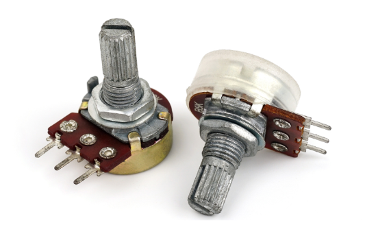
Variable Resistor and Potentiometer
A variable resistor is often also referred to as a potentiometer. A potentiometer, or variable resistor, is a resistor element whose resistance value can be adjusted, meaning it has adjustable or variable characteristics.
It is called a potentiometer because it changes the resistance to regulate the voltage or potential in a circuit, thereby producing different operating effects within the same circuit.
Variable Resistor in a Circuit
The primary functions of a variable resistor in a circuit can be seen in several key areas:
Current Regulation: By changing its resistance, it can limit or increase the flow of current, allowing for precise control of the current in a circuit.
Voltage Division: When used as a potentiometer, it can provide different voltage outputs by moving its wiper, enabling flexible voltage adjustment.
Signal Control: It is used to adjust volume in audio equipment, control brightness in lighting circuits, and regulate the speed of motors in control circuits.
Circuit Calibration: In test or experimental circuits, it can be used to fine-tune parameters to ensure the circuit reaches its ideal operating state.
Overall, the core function of a variable resistor is to control the current or voltage within a circuit by changing its resistance, thereby fulfilling the roles of regulation, division, and control.
Potentiometer Circuit Symbol and Pinout
Potentiometer Circuit Symbol
Every electronic component has a corresponding circuit symbol, and resistors are no exception. These symbols help us analyze and design different circuits more easily, both on paper and in simulation software. Here is the common circuit symbols for potentiometer(variable resistors) below.

Using the LED circuit as an example, you can more intuitively understand how a potentiometer is used in a circuit. The symbol shows that it typically has three terminals: two fixed terminals and one movable wiper. By adjusting the position of the wiper, you can change the resistance value and, in turn, control the circuit.
Potentiometer Pinout
The image below shows different types of potentiometers. Each potentiometer has three terminals, representing different pins. In the figure, pin 1 is marked as the positive power supply (VCC), pin 2 as the output terminal (OUTPUT), and pin 3 as the ground (GND).
Since all three terminals look identical externally, how can we distinguish between them? Generally, a multimeter is used as an auxiliary tool for testing.

How to Test the Potentiometer Pins with a Multimeter?
1. Set the multimeter to the resistance mode (ohm setting).
2. Connect the red probe to any terminal and the black probe to another terminal. Record the resistance value. Then keep the red probe in place and move the black probe to the third terminal, recording the resistance value again.
3. Rotate the potentiometer knob and observe the changes in resistance: if, between one terminal and the other two, one resistance remains fixed while the other changes continuously with the knob, and their sum equals the fixed resistance, then the terminal corresponding to the “continuously changing resistance” is the output (pin 2), while the two terminals connected by the fixed resistance are VCC (pin 1) and GND (pin 3), respectively.
What Are Variable Resistor Applications?
Variable resistors have a wide range of applications. Their main uses can be summarized as follows:
After understanding the basics of variable resistors, let's look at some common applications. Variable resistors have a wide range of uses. Their main applications can be summarized as follows:
- Volume Control
- Brightness Adjustment
- Sensor Signal Adjustment
- Circuit Debugging and Calibration
- Constant Current and Constant Voltage Sources
- Adjustable Filters and Audio Effects
- Home Appliance Control
Conclusion
A variable resistor, also known as a potentiometer, is a three-terminal electronic component with an adjustable resistance. Its main principle is to change the resistance by moving the sliding terminal between the two fixed resistors, thereby regulating the current or voltage.
Variable resistors come in a variety of shapes and sizes, suitable for different circuit design requirements. Heisener Electronics offers high-quality resistors and electronic components, ensuring reliable performance and a great user experience in industrial, research, and consumer electronics applications. Choosing Heisener’s variable resistors means obtaining an efficient and dependable electronic solution!
 0







 Login/Register

 BOM
 Cart